Solidworks Drawing Dimension Slot Length
DIMENSIONING:
Once you create the revolve feature from this sketch, the system will automatically add the diameter symbol. This double dimension technique is not restricted to just revolve feature sketches. Lastly, if you created the dimensions this way, and created a radius dimension instead of a diameter, or vice versa, you can change how it is displayed. I am having trouble dimensioning this part in Solidworks. The drawing is to be a manufacturing drawing, so needs to be very accurate. There cant be any tolerance stacking on any of the slots. I have tried using datum's, however to dimension all of the slots this way would over clutter the page imo.
NOTE: if you are not familiar with the layout of SolidWorks, thenclick here to familiarize yourself with the layout
Like all CAD programs, SolidWorks allows you to dimension the parts you create. Parts do not have to be dimensioned, but when you are making accurate drawings or are interested inmating parts, dimensions are extremely important. Luckily, SolidWorks makes it very easy to add and change dimensions. This tutorial will use 'link3slide.SLDPRT' from the parts.zip archive. You can use this tutorial for any part though.
Use file->open and browse to the folder that you downloaded the file to. Select'link3slide.SLDPRT' and click open:
You can only edit dimensions in sketch mode. To enter sketch mode you must first determine which sketch contains the dimension to change. Locate the sketch which contains the line/circle/arc you want to dimension. You can usually find the sketch under an 'extrude' in thefeature manager design tree. You will have to click the to reveal the sketch:
Right click on the sketch and select ‘edit sketch.’ You will notice that the rest of the part disappears or becomes transparent. Do not worry if some of the features of the part become transparent or disappear. They have NOT been deleted. They have simply been removed to simplify the screen and highlight the sketch you are currently working with.
You will now be in sketch mode and can use all the buttons on the right of the screen (picture rotated to save space):
If your view of the part is skewed, click the front view on the the standard view menu to rotate the sketch:
Your window should now look like this:
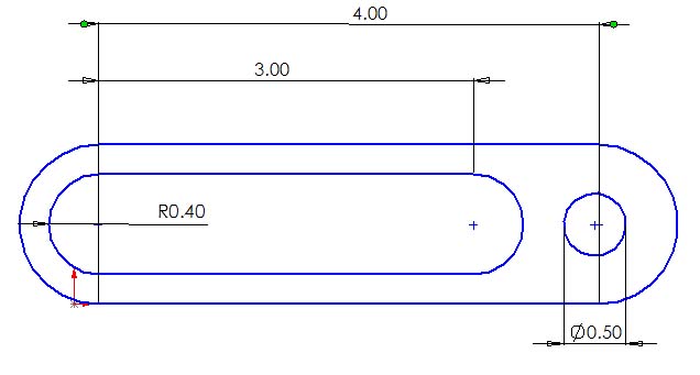
We will nowedit the diameter of the circular hole. We will edit it because the hole already has a dimension (.80in). This is specified by the lines coming off the circle with .80 on the bottom. To edit the dimension DOUBLE-CLICK on the .80. A box labeled 'Modify' will appear.
Erase .80 and enter .50. Click the green check or press enter.
Notice the hole gets smaller:
Editing Dimensions is great if dimensions are already defined in the sketch. But what if we want to add new dimensions? We will now learn how. First make sure you are in sketch mode. Follow the directions above if you are no longer in sketch mode. Notice that when you move your cursor over the sketch that certain features turn red. Any feature that turnsred can be dimensioned. These features are:
-a circle radius or diameter
-a line
-an arc
-a fillet/chamfer
-distance between two points
-distance between a line and a point
To add a dimension click the dimension button found on the sketch tools toolbar on the right of the screen. You will notice the cursor changes towhen you do this. We will now dimension the length of the slot. Move your cursor over the slot until either the top or bottom line turns red.The cursor will change again to signifying a line that can be dimensioned:

When it does, click with the left mouse button and drag up or down to select the placement of the leader and dimension. The placement is not critical. It is usually best to place it out of the way to keep the sketch neat and readable. When you are satisfied with the placement left-click again:
You can now edit the dimension exactly like above. Enter 3.00 and click the green arrow or press enter:
When you are done dimensioning, make sure to exit sketch mode by clicking the arrow in the top right corner of the screen:
You are now ready to try Dimensioning Exercise 1
Dimensioning Exercise 1:
Try adding the following dimensions for more practice:
Troubleshooting:

● If you notice that the dimension tool is not working or working erratically, you can always hit escape to unselect the dimension tool and start over again. This usually fixes any problem.
● If you mess up badly, you can always edit->undo. Likewise, if you want to go back to a certain point, you can use the undo list to see your undo options
Sketching it typically the basis for your models within Solidworks, but let’s be honest… it’s not always the most glamorous! I’m a firm believer that there is a fine line between efficiency and laziness. In your quest to do less work you actually become more efficient. So here are a few Solidworks Sketch Dimensioning tips to get you less work while you are sketching. [Also take a look at my post 10 Solidworks Sketching Tips You Want to Learn]
Solidworks Drawing Dimension Slot Length Rod
I am not one to do something twice, that is why I love the option to apply dimensions as I am defining the size of my sketched objects. Many of the sketch creation features (including lines, circles, rectangles, etc) include an option to Add dimensions. What this means is as you sketch Solidworks applies dimensions.

However, I only want dimensions when I actually specify the object size…. which is where the options come to the rescue. [Tools > Options > Sketch].
By checking Enable on screen numeric input on entity creation, text boxes will appear on the screen as you are sketching so that you can specify the size of the object on the screen. By enabling Create dimension only when valueis entered Solidworks will only convert your specified values into dimensions… exactly the workflow I want!
Other dimensioning tips…
- If the dimension is bouncing between the types… say horizontal to vertical to normal… as you move your mouse around the screen, right-click to lock the dimension orientation.
- To dimension to the virtual intersection of a rounded corner, first select the two lines and click Point to locate a point at the intersection… then dimension
- When dimensioning to a centerline continue moving the mouse to switch from the linear dimension to dimensioning the diameter
On the topic of sketch dimensions, when dimensioning between arcs and circles hold Shift as you select objects. By holding Shift, Solidworks creates dimensions tangent opposed to snapping to the center point.
To dimension the arc length, pick the two end points of the arc then the arc itself. For the arc opening angle, pick the two endpoints and the arc center point and pick the location of the dimension.
The Display / Delete Relations panel provides two great tools for working with your sketches. [Not saying Add Relation isn’t great, it’s just you don’t really need it with all the onscreen, in-context, heads-up options available now-a-days]
Fully Define Sketch attempts to do exactly as advertised…. it fully defines your sketch. It does so by applying what it deems as missing dimensions and relationships. What really makes this tool so powerful are the options. In the first section (Entities to Fully Define) notice that you can select all the objects (entities) in the sketch or be specific and only work with the currently selected objects. Clicking Calculate applies the missing relationships and dimensions.
Within the Relations section select the relationships you wish to have applied. Remember that by deselecting relations you may limit the software from fully defining the sketch. However, there are many times that certain relations cause the wrong (undesired) results. The great thing here is that you can always deselect relations, calculate, and if needed re-enable the relations and calculate again.
Use the Dimension section to define the type and placement for the generated dimensions. This includes Baseline, Chain, and Ordinate types and Above, Below, Right, and Left of the sketch for placement
A tip for using Fully Define sketch is to dimension and/or add relations to key sketch components BEFORE using the feature. Why? Then you are guaranteed to have the key areas defined and not leave it to the software to figure out. Use Fully Define sketch to take care of the clean up, finding the “open” entities and applying the missing details.

Solidworks Drawing Dimension Slot Length Chart

There will be times when you need to make modify to your sketch, but you can’t because the relationships are preventing you from making the desired changes. Consider using Display / Delete Relations select and delete multiple relations in one operation. As you select the relation in the list, it cross-highlights in the graphics window.
The Relations filter provides a quick method for limiting the list for just relations of a certain type
Another neat option, one I haven’t had that many opportunities to use, is the Replace option. Located in the Entities section, you can replace the selected entity with another that you have selected in the graphics window. If it doesn’t work SolidWorks will tell you so by showing a status of invalid.
Last tip for today is to try the new Instant2D feature added in SolidWorks 2016. With Instant2D active when you select the dimension value you can modify its value in the onscreen input box.
You can also use the Instant2D Rulers to make constrained adjustments of the existing dimensions. After selecting the dimension, click-and-drag the dimension handle located at the end of the leader. The Instant2D handle automatically appears. As you drag over the ruler, your cursor snaps to the lines, meaning you can make small incremental changes (small ticks) or large incremental changes (large ticks). When you release the mouse the sketch updates.
Feature Image “Sketch” by Ian Normand